1.5
Attach FinalKey-LED and power-LED like "red heart"
or "green miracle"
Before programming your hex - file
you should ...
| What |
Why |
|
| 1. |
Check source code. |
You will put all your secret
passwords to this hardware. You should make sure that nobody
introduced a backdoor or malicious code. |
| 2. |
Set your language
preferences. |
If you dont set your language
preferences you have to go with dusteds standard setup
(danish and us) This might keep you from using special characters or it might keep you from using FinalKey at all. |
| 3. |
Compile it yourself. |
If somebody else hands you a
hex-file you should trust her/him. If you dont trust her/him
compile it yourself. And why should you trust somebody from the internet. Be paranoid when your passwords are at stake. |
| 4. |
Use open source compiler,
avoid closed source code. |
Use code you can read. Open
source compiler can be checked. Closed source software may
do some strange things to your code. |
| 5. |
Read the documentation up to
the very end. |
If you just read the starting
part you will notice some missing parts in the middle and
some technics not available for you in the process ahead of
you. Some minutes of reading will save you hours of
frustration. |
No, I am not paranoid, i will do whatever you propose.
<- So why do you want a FinalKey?
Why is this done first?
If you solder all components to your board first it is much more
difficult to access all programming pins on your arduino.
With a clean board all pins are easily accessible.
There are two ways to program arduino micro pro:
Why you should not use USB : Anybody with access to the reset pin or reset-button can reprogram your arduino and read the contence of your eeprom without taking everything apart. Yes its encryptet, but with enough computational power this should not be a problem in the long run. If you go with ISP it is complicated to get the contence of your eeprom. Therefore ISP programming makes FinalKey more secure.
If you just want to see if Finalkey is the solution you are
looking for, you can test it with USB-programming. You will always
be able to program other stuff on your arduino pro micro
afterwards because your bootloader will still be there. Keep in
mind that for a real test you need the eeprom, 2x4.7kOhm, a
FinalKey-button and an LED with an appropriate resistor connected.
Programming via USB is done with arduino IDE or any other
compatible soft.
Just select your program port (should be ttyACM* on linux, NOT
ttyUSB*),
then select your board (arduino pro micro),
press the reset button twice and start uploading FinalKey software
within 8 seconds.
If you have any other bootloader on your board, which is NOT
started for 8 seconds after pressing the rest button twice, follow
its instructions ...
Using ISP-programming will overwrite your bootloader. If you do
so anybody wanting the contents of your eeprom has much more work
ahead to get it. Its not impossible to read the eeprom but your
Finalkey has a much better protection against attacks after using
ISP for programming.
You can follow dusteds setup
or use the following procedure:
Overview :
Setup any arduino with atmega 328 or higher as ISP Programmer or
use any other ISP programmer.
Connect 6 programming lines
Run avrdude to push FinalKey software to arduini pro micro.
Details :
Setup any Atmega 328 based arduino as ISP Programmer (software is in examples of arduino IDE) or use the ISP programmer of your choice.
Needed connections : GND, VCC, RST, MISO, MOSI, SCLK.
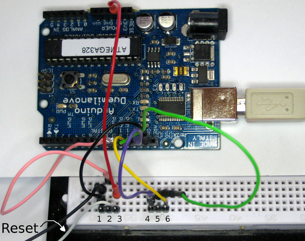
In the following images an old arduino due is used. Many other
arduinos can do it too, only boards with atmegas below 328 are not
able to use the ISP programming software. If in doubt read your
manual. And check arduinos ISP software for the pins to use.
Attention : If you program your
arduino pro micro with ISP it will kill your bootloader.
This is a security feature not a bug!
There is no way back by easy means to get any other software on your board afterwards. This is a one way action, if you dont have the hardware and the know how to setup another bootloader. You better make sure that you have the right hex- file with the language/keyboard settings you want!
You have been warned.
Connect 2x3 pins (1/2/3 and 4/5/6) and a Reset button on a
breadboard like this including 4 spaces between the two grouped
pins (see bottom of the following image):
| pin name: | arduino
as ISP Atmega 328/Duemilanove |
breadboard pin NR |
color used |
FinalkKey arduino pro micro, V3 |
| GND | GND | 1 |
black |
GND |
| slave reset | 10 | 2 |
light gray/pink | RST |
| VCC/5V | 5V | 3 |
red | VCC |
| MOSI | 11 | 4 |
yellow | 16 |
| MISO | 12 | 5 |
green |
14 |
| SCK | 13 | 6 |
violett |
15 |
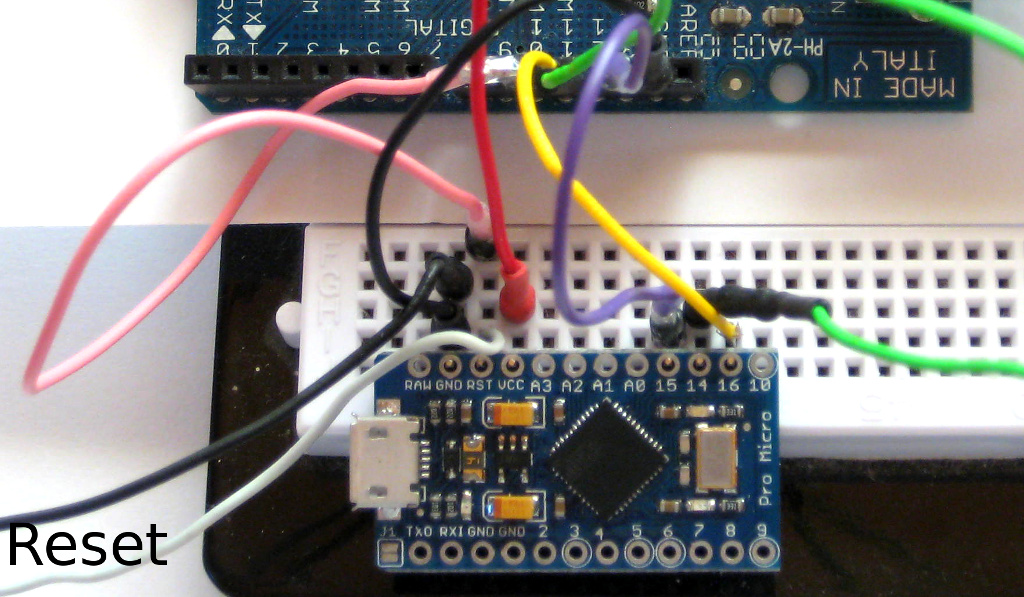
Make sure that pins are aligned with GND/RST/VCC and 15/14/16
like shown above. The green wire is connected to 12 on arduino
due! As it is isolated with black shrink wrap the image is
misleading on the due part. The green wire seems to be
connected to 10, but it isnt. If you want to be on the safe side
: solder your wires for programming and desolder afterwards.
Dont solder pins, they are hard to remove. Single wires can be
desoldered much easier.
Doublecheck your connections, especially powerlines (GND and VCC).
If you swap those, you might kill your board. All other lines
interchanged will only wind up in not programming your board.
You dont need any soldering with this setup, just let your board
hang on the pins.
If this sounds risky to you, yes it is. If you have a cat, a dog,
little children or any other critters around, dont do it :D .
Dont remove your board before avrdude has finished its job which
takes about a minute.
Avrdude will let you know you when the job is done.
The following run is from linux but should be similar on any system capable of running avrdude:
Press the reset button TWICE (DoubleClick) and run avrdude within 8 seconds with a line like this :
avrdude -c stk500v1 -b 19200 -P /dev/ttyUSB1 -p m32u4 -U
flash:w:FinalKey.hex
| command |
intent |
| -c stk500v1 | => Use arduino due
as ISP (see avrdude.conf for other ISP-hardware) |
| -b 19200 | => Set speed to
19200 baud. Higher speeds are possible but may fail. 19200
never failed me. |
| -P /dev/ttyUSB1 | => Use port /dev/ttyUSB1, the one your arduino due or your ISP programmmer is connected to your pc . |
| -p m32u4 |
=> Tell avrdude to use settings for atmega 32u4 on your arduino pro micro/your FinalKey hardware. |
| -U_flash:w:FinalKey.hex | => Flash/write your hex
file (use full path if you are not inside the folder with
your hex-file). Any name will do, as long as it is a valid FinalKey-hex-file. Make sure that you use a file with your language settings. If your language is not within the usable laguages of your hex-file you are stuck with the languages available in the programmed file. If you flash anything else, well you are stuck with it then, or write a new bootloader to your arduino pro micro. |
Adopt the command to your actual settings.
Usually the first run does not work, at least for me. But a
second run immediately afterwards within the 8 seconds always
does.
You dont have to press reset again, just restart the avrdude command for a second time!
If you missed the 8 seconds and failed, DONT PANIC. Just start
again with another doubleclick on the reset button ...
If you succeed, avrdude will tell you while it is running :
avrdude: AVR device
initialized and ready to accept instructions
Reading |
################################################## | 100% 0.05s
avrdude: Device signature =
0x1e9587
avrdude: NOTE: "flash" memory
has been specified, an erase cycle will be performed
To disable this feature, specify the -D option.
avrdude: erasing chip
avrdude: reading input file
"FinalKey.hex"
avrdude: input file
FinalKey.hex auto detected as Intel Hex
avrdude: writing flash (26170
bytes):
Writing |
################################################## | 100% 31.97s
avrdude: 26170 bytes of flash
written
avrdude: verifying flash
memory against FinalKey.hex:
avrdude: load data flash data
from input file FinalKey.hex:
avrdude: input file
FinalKey.hex auto detected as Intel Hex
avrdude: input file
FinalKey.hex contains 26170 bytes
avrdude: reading on-chip
flash data:
Reading |
################################################## | 100% 19.51s
avrdude: verifying ...
avrdude: 26170 bytes of flash
verified
avrdude: safemode: Fuses OK
(E:CB, H:D8, L:FF)
avrdude done. Thank
you.
If you fail in the very first run, as i always do, avrdude will
let you know :
avrdude: stk500_getsync()
attempt 1 of 10: not in sync: resp=0x15
avrdude: stk500_getsync()
attempt 2 of 10: not in sync: resp=0x15
avrdude: stk500_getparm():
(a) protocol error, expect=0x14, resp=0x14
avrdude: stk500_getparm():
(a) protocol error, expect=0x14, resp=0x01
avrdude: stk500_initialize():
(a) protocol error, expect=0x14, resp=0x10
avrdude: initialization
failed, rc=-1
Double check connections and try again, or use -F to override
this check.
avrdude: stk500_disable():
unknown response=0x12
avrdude done. Thank
you.
Again : DONT PANIC, just give it another try
Have some tee and a cookie, smile.
You cannot give it a testrun now because the eeprom is missing
and the other finalkey parts too.
A minimal affirmation that you succeded is the missing bootloader.
You will not be able to enter it any more.
Lets get the missing components connected => step 1.2 and more
:
1.2.1 Bend pins of your eeprom
1.2.2 Glue eeprom on atmega chip
1.2.3 Solder eeprom to board
1.2.4 Fill gaps between eeprom legs and board with
two-component-glue
Bend pins of your eeprom in two steps. First flatten all legs
until they are almost parallel to the topside of your eeprom. Then
bend the down tips. As there is an atmega between the board and
the eeprom the tips of your eeprom should be well below the bottom
of the chip. It should look like this afterwards :
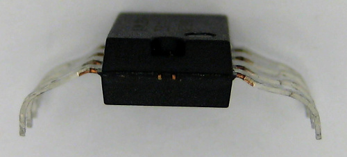
Eeprom with bended legs.
If you bend it according to your arduino board it will fit without falling off if you turn the board around.
Glue it to your board now and solder all 8 pins. Use any glue
that helps keeping your eeprom in place. Use the minimum glue to
do the job.
Fill up the gaps AFTER soldering between eeprom legs and board
with 2-component epoxy glue. This will give much mor stability. If
you dont do it, it will be hard to get repair glue into the gaps.
If you dont fill up empty space at all then eeprom legs and solder
points alone have to take pressure from outside.
Dont use too much glue and make sure
that GND and VCC connetors are not covered or filled up.
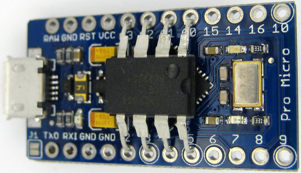
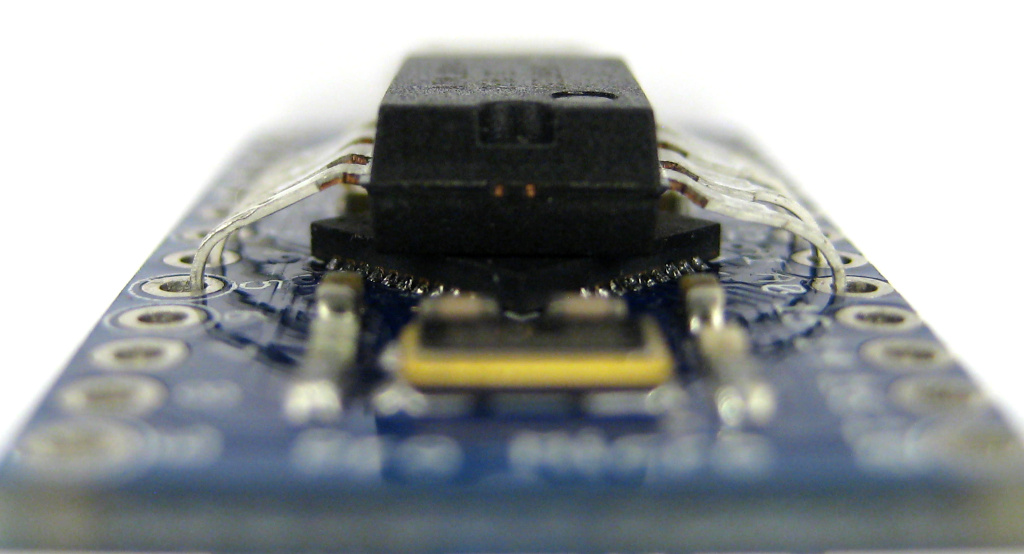
Soldered and glued eeprom :
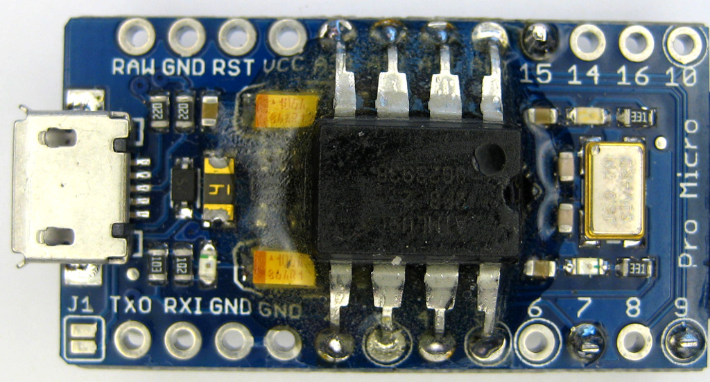
If you are a good observer you will notice that there is a
finalkey-button already connected to pin 7 and 9 and pin 15 is
soldered too ( with 2x4.7kOhm ...).These components live on the
other side. Lets see how this is done :
Take a big pushbutton about 1cm square,
test your button first. If you cut off the wrong legs you need
another switch ...
Cut off legs on one side,
bend legs on the other side,
solder it to back of arduino pro micro to pin 7 and 9 on the empty
side.
Solder your button before soldering resistors. This prevents you
from placement errors. Pin 15 used for your 4.7 kOhm components
sits right besides the button (well its below the button in the
following image)!
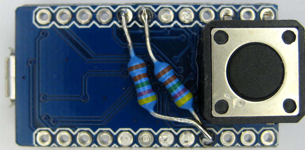
Arduino Pro Micro empty "backside" with FinalKey-button soldered
(and 2x4.7 kOhm ...)
This will be the top when you use your key.
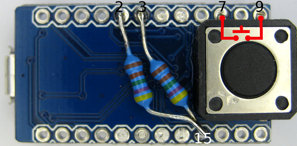
Stick one end of your 4.7 kOhm resistor first into pin hole 15 and solder it.
Cut off the other end so that it can still be soldered to pin 3
and does not overhang the board.
Solder it to pin 3.
Solder another 4.7 kOhm ontop the wire sticking in pin hole 15.
Cut off its other end.
Solder it to pin 2 of your board.
It should look like the image above (1.3)
To get a working FinalKey the only part missing is the finalkey-led. If you dont need anything else, solder it with an appropriate resistor in series to pin 10 and VCC (+5V), cover your board with repair glue and you are done. If you want something shiny and blinking go with red heart or green miracle or use colors and design of your own choice.
Have Phun !
Design and hardware extensions used for Red Heart, Alien Artefact and Green Miracle : tc (thunderchild), Nov 2014 |
All praise and credit for FinalKey hardware and software go to dusted.