| Step |
What |
Why |
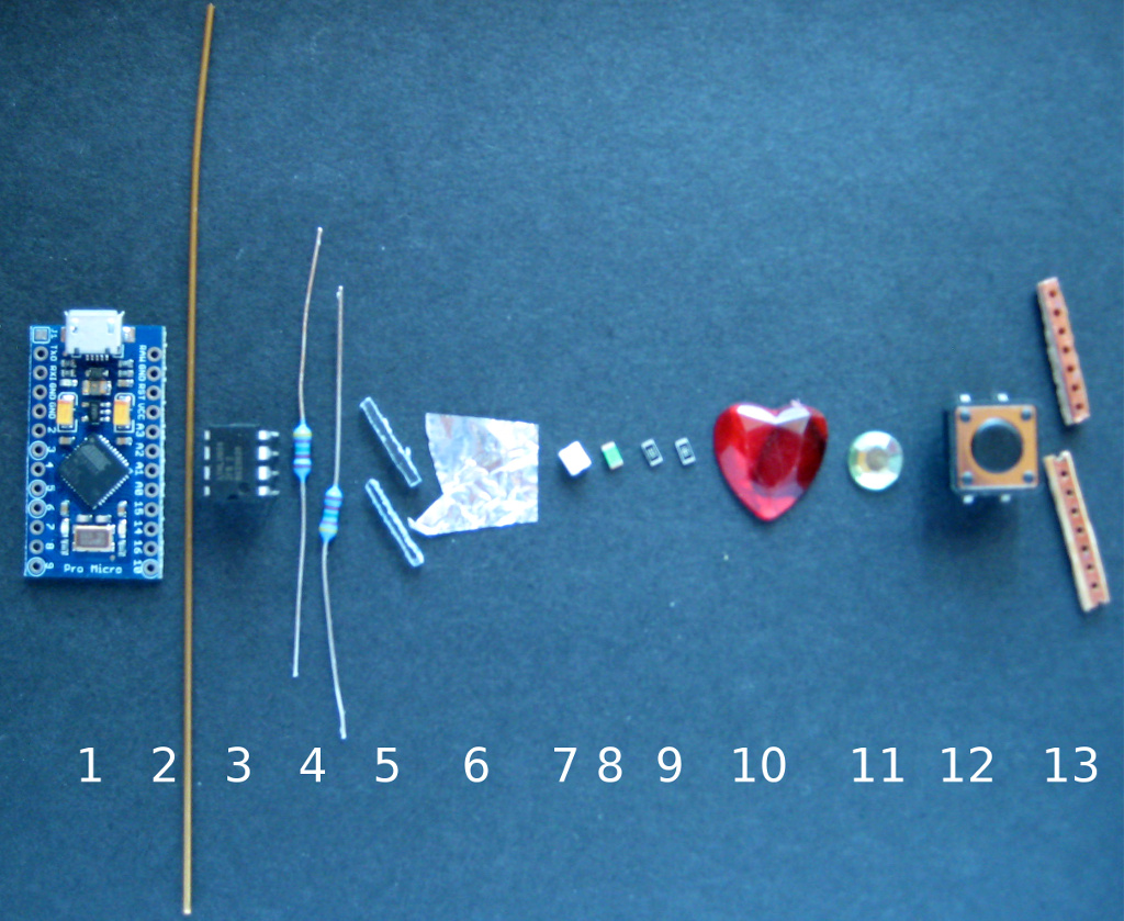
| Brass rod/wire, 1mm thick |
Brass rod (1mm) is easy to
bend and strong enogh to make a proper handle. Thinner brass
rod is too soft. Thicker brass rod is very hard to bend.
Aluminium is too soft. Anything with plain iron will
rust. High quality steel is too hard. Silver is too soft. Go
for gold alloy, used for tooth crown, if you have the money.
Its even shinier than brass ;-) |
|
| 2.0 |
dremel or sand the edges of
arduino pro to get "round" soft edges at the usb side of the
board |
It is close to impossible to
bend the rod to a 90° angle. Its always a bit round at
the edge. As you will want a close fit you have to get rid
of the sharp edges at the usb port side of the circuit
board. This is not a problem on the other side (not usb ...). There is no 90 degree angle for the brass rod. |
| 2.1 |
cut about 12 cm from a brass
rod of 1mm diameter |
Do this first because its
handy to have an extra part to handle the arduino in all
steps following. Dont use anthing thinner, because its too
fragile then. Dont use anything thicker as 1 mm as it will
be very hard to bend. |
| 2.2 |
bend 3-5 mm as tight and
close to 90 degrees for the usb side as possible |
If you sanded the edges
properly, the rod will have a tight fit which is essitial
for handling the board afterwards. These bended parts of the
rod take the load for any drag on the opposite side. If you
dont have tthem the glue at the sides of the board has to
take the load alone. This is not prefereable. |
| 2.3 |
bend it to a curve on the
other side with a distance of 1-2 cm from the board |
If you need a large curved
rod to even put your finger through it, make it larger. I
only want it to hang an a hook or to attach it to a key
ring. |
| 2.4 |
bend it as tight and close to
90 degrees as possible for the other edge close to usb. Cut
off the part which does not fit :). |
see 2.2 Its no problem if the rod just slightly touches the usb port as it is grounded. But the rod should not move away from the board because the bent part is too long. Remember : a tight fit is the goal. |
| 2.5 |
make sure to have a flat
construction that fits exactly around the circuit board |
If your construction is not
flat you will not be able to glue it around the circuit
board. Instead you will be ruining your fingers, the circuit
board, your clothes and anything close to your handling area
in the attempt to get it done. |
| 2.6 |
glue it around the board and
let it cure. Make sure that it does not touch any
wires/conducting parts. |
I always use a strong 24 hour
curing 2 component glue to make sure that i get a strong and
durable connection. Dont use super glue or any stuff which
goes hard like a crystal after curing. Its not very usefull
for parts with large gaps. And dont use anything soft like
regular paper glue. It will not even hold the circuit board
alone if bad luck hits you. Hot glue might be an alternative
if you have a gluegun with a very fine tip. Otherwise you
will find glue all over the place. And its not as strong as
i want the bonding to be. |
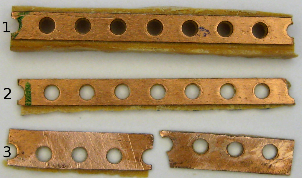
1) Get some junk stripboard with 5 to 7 holes (1)
2) Sand it down until you have only a very thin film on the copper
line left. (2),
Dont sand down the copper, only the opposite!
Make sure to leave a thin film of isolating
material on the copper.
If you sand it up to the copper you will have a
nice chance to create a short.
3) Cut off two lines and cut these in half. (3). Thats the
middle where the led will sit.
4) Cut off the small parts until you have 2 straight lines at
soldering position.
5) Cut one of the pieces into half again where the resistor will
sit.
| Step |
What |
Why |
| 4.0 |
Arrange your copper parts
with small gaps of about 1 mm up to 2 mm in a line and
solder your parts.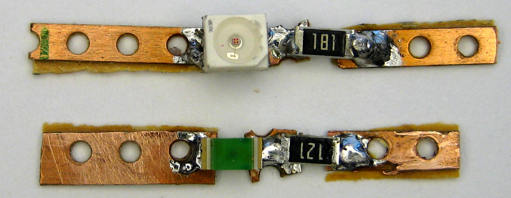 |
This line will fit onto the
arduino micro pro board. Any stripboard with 2.54 mm distance between holes will do it. Otherwise you have to recalculate length. Anyway, only one hole has to fit exactly : GND. The other end will be connected by a wire, so there does not have to be an exact match of holes at the ends of our mini-led-board with the arduino board. Cut off any overhanging copper. |
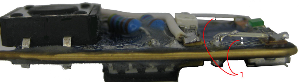
| 4.1 |
Make sure that you have nice
gaps below your components : Side View : 1 -red LED board , 2- green LED board, R - Resistor 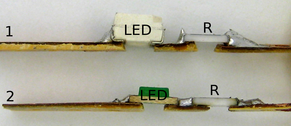 |
The two gaps are the mounting
places for resistor and led. The resistor has to have
a minimum of 160 Ohm. A red LED needs about 1.8 Volt at 20 mA. As we are running our finalkey from usb port, 5 Volt will kill it without a resistor taking the voltage up to 5 Volt. R=U/I -> R= 3.2Volt / 0.02 mA -> R=160. Depending on your LED and its brighness you can go up to several hundred Ohm and it will still be bright. Nowaday LEDs might blind you if you run them with maximum allowed current. I used a 180 Ohm resistor which protects the red led and still allows enough current to make it shine bright. The green LED is not as bright as the red one. I just want a faint glow for power. |
| 4.2 |
Test your boards with 5 Volts
and mark the working polarity on your boards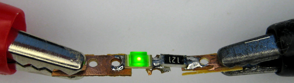 |
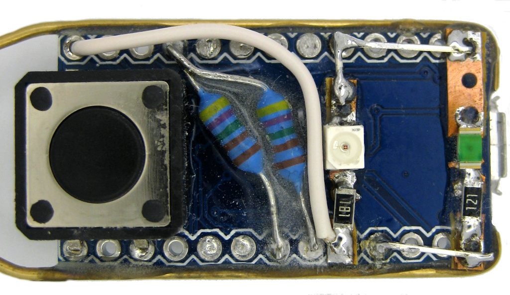
| 5.1 |
Glue your boards to your
arduino board between resistors and usb port.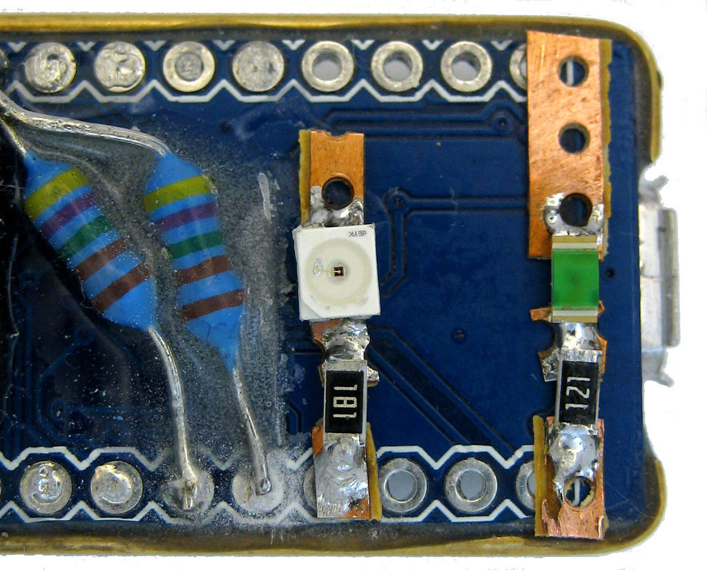 |
As we need some space for the
gemstones, the red LED goes to the middle and the green LED
goes close to usb port |
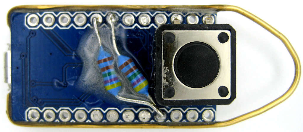
| 5.2 |
Solder mini striboards
 Make sure to leave a gap
between your wires and arduino board (1):
 |
|
| 5.3 |
Test your board. If you want
to be on the safe side just use 5 Volts on arduinos usb-port If this works : -> no smoking components, no LED burnout ->but a short blink for red and constant light from green LED/power-LED then : Test it on your pc-usb-port with FinalKey software running (arduino drivers and putty on WinX or dusteds JAVA-Gui on any OS or Terminal on Linux) |
| What |
Why |
|
| 6.0 |
Prepare red Gemstone :
scratch a square from the reflecting back
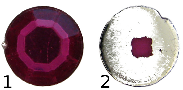 1: top view 2 : bottom view with scratched square |
Most cheap gemstones have a
refleting back. If you glue this on your LED no light will
shine through. So you better scratch some stuff off where
your LED will sit. The FinalKey LED should be the most prominent part to watch. Its the brightest LED and the biggest source of light. |
| 6.1 |
Prepare green gemstone :
Cut off a rectangle from a round gemstone. Scratch off a square in the middle of the back-reflector.  3 : Top view, 4 : after cutting, scratching 5 : bottom view |
The power-LED is used just to
make sure everything is connected proberly. The LED just
gives a faint glow and has a small footprint. Adjust this to your needs and your surroundings. |
| 6.2 |
Glue gemstones on LEDs : red
on red, green on green ... Use fast curing two component glue. If possible fill all gaps between gemstones and arduino board.  |
If your glue needs a long
time to cure you have to fix the gemstones on the LEDs.
Otherwise they tend to wander to a place where you dont want
them to stay. Fixing these parts is a pain. So you better
use fast curing glue (3-5 Minutes is ok with me waiting and
keeping stuff in place). You should be able to see the leds. If you cant see them you forgot to scratch the back-reflector ... rip off gemstones before glue is hardening. |
| 6.3 |
Dont move until glue is cured
:-). |
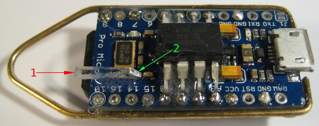
arduino pro micro with one of the two
lightpipes mounted :
1 : acrylic pole sends
light from led to surface, works as light pipe.
2: aluminium foil
mirrors light into your light pipe.
| Nr. |
What |
Why |
| 7.0 |
Cut some acrylic of a thin
sheet 1x1mm up to 2x2mm, 1cm long |
This tiny pole will act as a
light pipe and guide light from an led to the surface of
your FinalKey. The smaller its cross section is the better
it will work. See your old physics book at : total internal
reflection. The bigger your cross section gets the more
light will escape. |
| 7.1 |
Cut one end at an angle of
about 45° |
This end will act as a
mirror. It will sit exactly above the led. If you want to make it perfect, polish all sides. The smoother the surface the more light will stay inside your light pipe. |
| 7.2 |
Glue a small square of
aluminium foil onto the 45 angle part (see
image at 2). Or put a long strip of foil on the upper part of your light pipe. Dont cover the whole pipe because you are most likely creating a short when you glue this on your board. |
This is the mirror ... it
will reflect light from the LED into your light pipe. |
| 7.3 |
Glue your mirror on top of
the led |
Put the aluminium exactly
above the led. If you miss the LED most of its light will
escape. If you want even more light put some more aluminium on top of your pipe and at its side. Dont put anything below. Chances are high that you short some contacts and brick your arduino. If you put aluminium on the sides be carefull to only cover the upper part and dont come close to the bottom -> avoid short circuits on arduino! |
| 7.4 |
Mount another light pipe on
top of the second LED. Cover both with aluminium foil without any contact to components on your board.  |
|
| 7.5 |
Let it cure |
If everything is cured, cover your creation with repair glue. Dont cover your gemstones. The stuff i used cures in about 8 to 10 minutes.
After this time there is about an hour to cut off stuff easily without damaging the main construction. After about an hour you cant cut it, you have to sand or dremel it. So use your time carefully. Its best to make a test before using repair glue on your board.
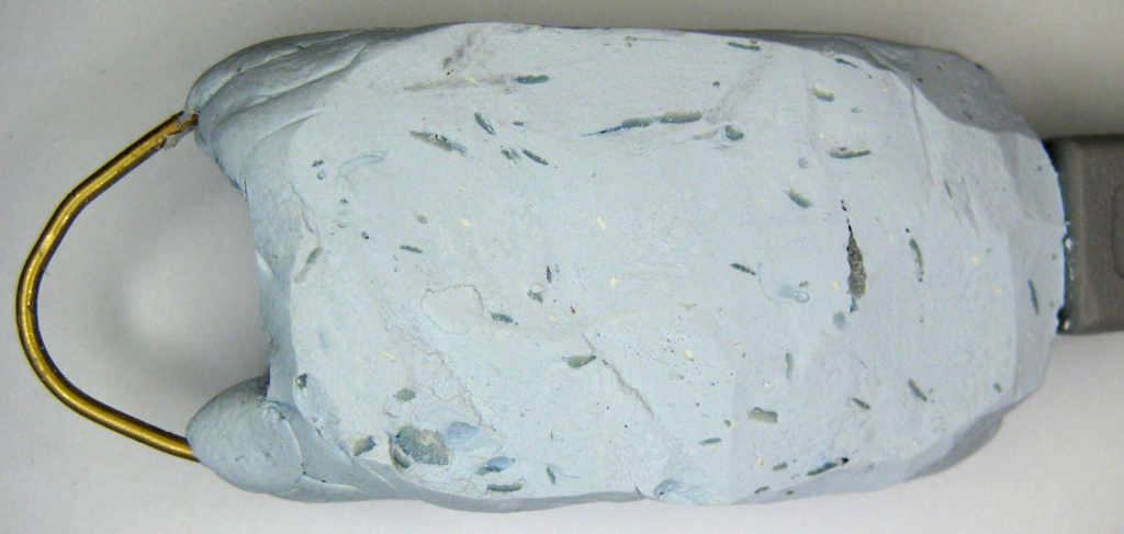
9.1 Sand it down to the properties you prefer
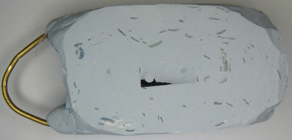
sand it down until you get a glimpse of the eeprom
sand it until you just remove the eeprom text. If go down even
more you might ruin the eeprom chip!
STOP SANDING BACKSIDE NOW!
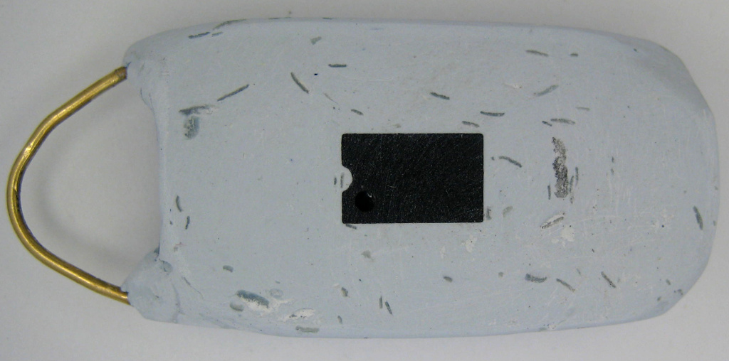
Frontside sanded but not polished :
Start polishing now. Use a silikon polisher, very fine sanding
paper or whatever is appropriate for your repair glue. Be careful
not to scratch your gemstones. You can do it on purpose to get
another look. If you dont like your scratched gemstone you can
cover it with transparent varnish. It will not be as shiny as the
original but can come close.
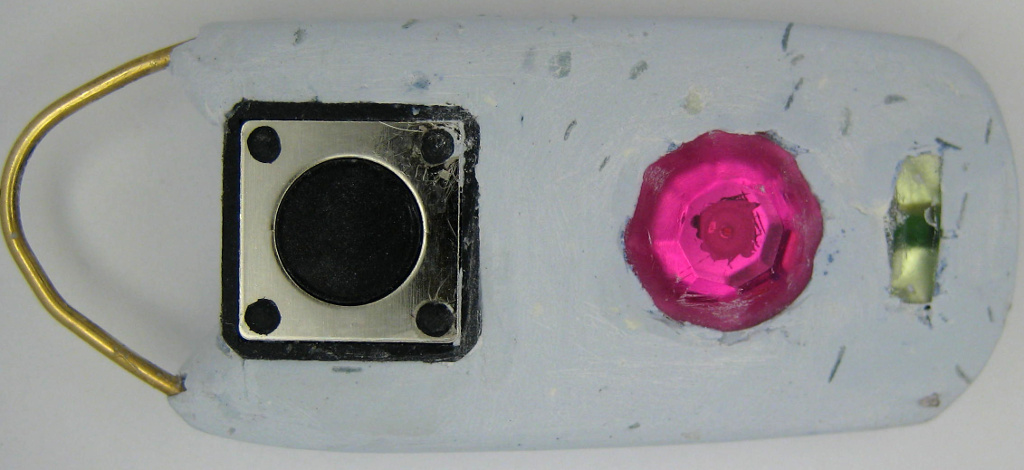
Coloring :
To be on the safe side put a cover on top of the switch first.
Cut some plastic sheet and glue it to the edge of the button. Be
careful not to come close to the button itself. With my button i
used the outer black square to put glue on. As you can see fom the
green speckles on this part of the button i didnt wait for it to
cure. So some green particles were glued there too. If you use
some soft glue these particles can be removed easily. Always keep
the usb connector down while using glitter. If you dont you will
mess up the usb port. You can cover this too if you want to. If
you are carefull you dont need to cover it.
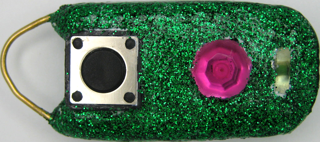
If you go for a shiny glitter-look put some clear varnish on your
FinalKey first and sprinkle the glittering stuff on the wet
surface. Repeat this until all parts you want to color are
covered. Let it cure before you apply another layer otherwise you
will just smear and uncover parts which you considered done. The
glittering stuff will give a rough surface. Put some more layers
of clear varnish on top until you have the look and feel you want.
And again : LET IT CURE before going for another layer. Failed
speckles of glitter can be scratched of easily if you use common
nail varnish. For a tougher surface use spar varnish used for
boats or use resin.
Almost done :
Enjoy !
Design and hardware extensions used for Red Heart, Alien Artefact and Green Miracle : tc (thunderchild), Nov 2014 |
All praise and credit for FinalKey hardware and software go to dusted.