program
finalkey software or -> see dusteds setup,
solder eeprom to arduino board
solder big pushbutton to
arduino board
solder 2 x 4.7 kOhm,
| Step |
What |
Why |
| 2.0 |
Cut about 12 cm from a brass
rod of 1mm diameter. Make it longer if you want to hold with your finger. |
Brass rod (1mm) is easy to
bend and strong enogh to make a proper handle. Thinner brass
rod is too soft. Thicker brass rod is very hard to bend.
Aluminium is too soft. Anything with plain iron will
rust. High quality steel is too hard. Silver is too soft. Go
for gold alloy, used for tooth crown, if you have the money.
Its even shinier than brass ;-) |
| 2.1 |
Dremel or sand the edges of
arduino pro to get "round" soft edges at the usb side of the
board. |
It is close to impossible to
bend the rod to a 90° angle. Its always a bit round at
the edge. As you will want a close fit you have to get rid
of the sharp edges at the usb port side of the circuit
board. This is not a problem on the other side (not usb ...). There is no 90 degree angle for the brass rod. |
| 2.2 |
Bend 3-5 mm as tight and
close to 90 degrees for the usb side as possible |
If you sanded the edges
properly, the rod will have a tight fit which is essitial
for handling the board afterwards. These bended parts of the
rod take the load for any drag on the opposite side. If you
dont have tthem the glue at the sides of the board has to
take the load alone. This is not prefereable. |
| 2.3 |
Bend it to a curve on the
other side with a distance of 1-2 cm from the board |
If you need a large curved
rod to even put your finger through it, make it larger. I
only want it to hang an a hook or to attach it to a key
ring. |
| 2.4 |
Bend it as tight and close to
90 degrees as possible for the other edge close to usb. Cut off the part which does not fit :). 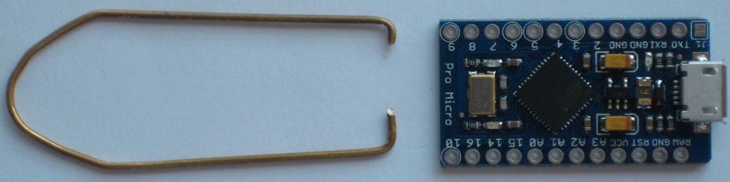 |
see 2.2 Its no problem if the rod just slightly touches the usb port as it is grounded. But the rod should not move away from the board because the bent part is too long. Remember : a tight fit is the goal. If you bend it just a little too much inwards it will cling to your board by itself (see image in the left). Gluing will be easy then. If you don't have a tight fit, you will have a hard time fixing the rod when you try to glue it to arduino. |
| 2.5 |
Make sure to have a flat
construction that fits exactly around the circuit board :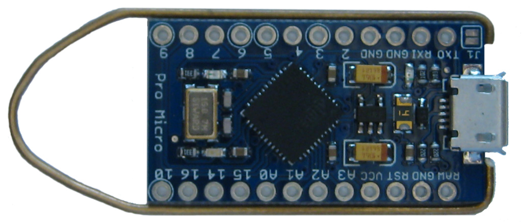 |
If your construction is not
flat you will not be able to glue it around the circuit
board. Instead you will be ruining your fingers, the circuit
board, your clothes and anything close to your handling area
in the attempt to get it done. A simple test : lift your
arduino board wihout touching the rod. If the rod sticks to
the board without moving you are ready to go for the glue. |
| 2.6 |
Glue it around the board and
let it cure. Make sure that it does not touch any
wires/conducting parts. You will have a nice handle now for all the steps following. |
I always use a strong 24 hour
curing 2 component glue to make sure that i get a strong and
durable connection. Dont use super glue or any stuff which
goes hard like a crystal after curing. Its not very usefull
for parts with large gaps. And dont use anything soft like
regular paper glue. It will not even hold the circuit board
alone if bad luck hits you. Hot glue might be an alternative
if you have a gluegun with a very fine tip. Otherwise you
will find glue all over the place. And its not as strong as
i want the bonding to be. If you dont attach this handle all coloring and varnishing actions will be a pain. And you can't put your key on a chain or necklace. |
| Step |
What |
Why |
| 3.0 |
Cut off a single line
stripboard, seven holes long.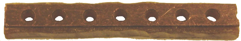 |
This line will fit onto the
arduino micro pro board. Any stripboard with 2.54 mm distance between holes will do it. Otherwise you have to recalculate length. Anyway, only one hole has to fit exactly : +5V. The other end will be connected by a wire, so there does not have to be an exact match of holes at the ends of our mini-led-board with the arduino board. |
| 3.1 |
Cut the copper line at 2
holes, one exactly in the middle, thats where the led goes.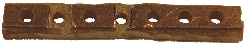 |
The two cuts are the mounting
places for a resistor and the led. The resistor has to have
a minimum of 160 Ohm. Red LEDs needs about 1.8 Volt at 20 mA. As we are running our finalkey from usb port, 5 Volt will kill it without a resistor taking the voltage up to 5 Volt. R=U/I -> R= 3.2Volt / 0.02 mA -> R=U/I=160. Depending on your LED and its brighness you can go up to several hundred Ohm and it will still be bright. Nowadays LEDs might blind you if you run them with maximum allowed current. |
| 3.2 |
Solder resistor and led over
cuts, test it at 5 Volts ! Resolder if necessary. Kathode (GND) goes to Pin 10 of arduino for your FinlKey LED. 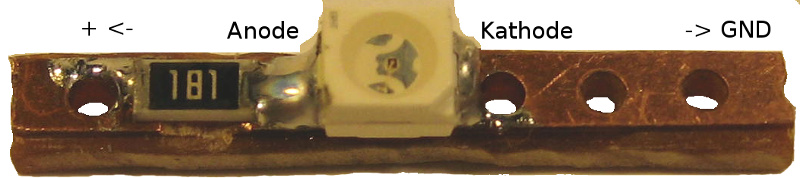 |
I used a 180 Ohm resistor
which protects the red led and still allows enough current
to make it shine bright. Dont connect it to arduino yet. NO GLUE, NO SOLDERING to arduino. You have to glue fiber optics to red power led first. This is located to some extent below the finalkey led stripboard. See image 4.4. Attention reset button users : If you want a reset button you better solder the resistor to the right and cut off 2 holes from the stripboard on the left. You will need this space for the reset button |
| 3.3 |
Build another one with a
green LED for power-LED. Anode goes to +5V/VCC. Kathode/GND goes to GND. |
|
| 3.4 |
Test both strips before
soldering them onto your arduino. Available connectors on your arduino board : 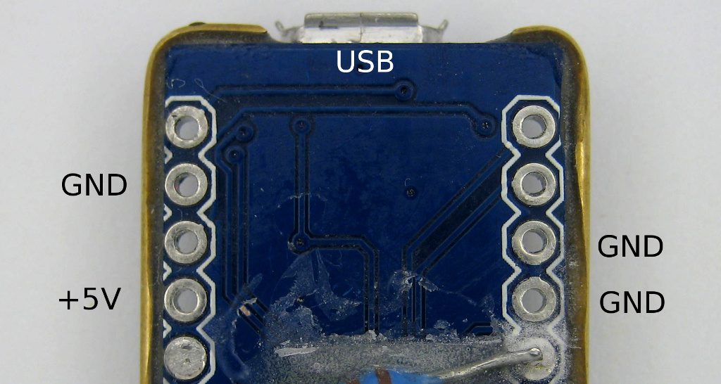 |
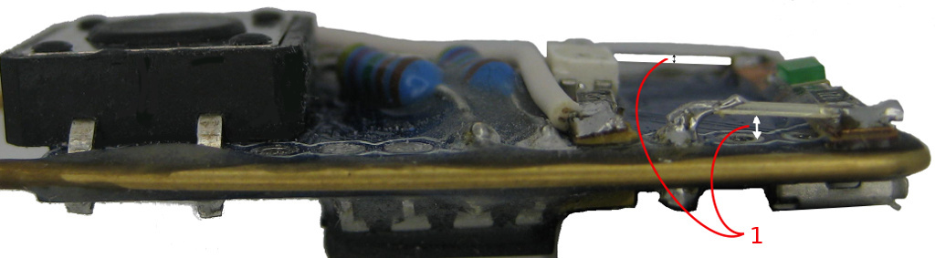
Led-stripboards soldered, side-view. The image is taken from the
Green Miracle. Stripboards are sanded to a minimum. If you dont
sand them the stripboards will raise LEDs and gemstones.
Make sure not to short anything by leaving a clear gap between
arduino board and your wires (1).
| 4.1 |
Glue both strips to arduino.
Test both before soldering. |
You can place them on your
board so that at least one hole matches with arduino. Or you
can place them wherever you like and use 4 wires to connect
them. I recommend to use at least one matching hole :
FinalKey-led and VCC(+5V). Keep in mind that you need some
room for the big FinalKey-led-gemstone. It sits in the
middle between button and power LED in my setup. |
| 4.2 |
Solder LED connections to arduino. | Finalkey-LED needs +5V/VCC,
Kathode goes to pin 10 (needs a wire, the white one in the
image above)! Power LED needs +5V and GND (some short wires like cut off led wires will do it) |
arduino pro micro with one of the two
lightpipes mounted :
1 : acrylic pole sends
light from led to surface, it works as light pipe.
2: aluminium foil
mirrors light into your light pipe.
| Nr. |
What |
Why |
| 6.0 |
Cut some acrylic of a thin
sheet 1x1mm up to 2x2mm, 1cm long (see
image above) |
This tiny pole will act as a
light pipe and guide light from an led to the surface of
your FinalKey. The smaller its cross section is the better
it will work. See your old physics book at : total internal
reflection. The bigger your cross section gets the more
light will escape. |
| 6.1 |
Cut one end at an angle of
about 45° |
This end will act as a
mirror. It will sit exactly above the led. If you want to make it perfect, polish all sides. The smoother the surface the more light will stay inside your light pipe. |
| 6.2 |
Glue a small square of
aluminium foil onto the 45 angle part (see
image at 2). Or put a long strip of foil on the upper part of your light pipe. Dont cover the whole pipe because you are most likely creating a short when you glue this on your board. |
This is the mirror ... it
will reflect light from the LED into your light pipe. |
| 6.3 |
Glue your mirror on top of
the led (see below, 6.4, and the
image above) |
Put the aluminium exactly
above the led. If you miss the LED most of its light will
escape. If you want even more light put some more aluminium on top of your pipe and at its side. Dont put anything below. Chances are high that you short some contacts and brick your arduino. If you put aluminium on the sides be carefull to only cover the upper part and dont come close to the bottom -> avoid short circuits on arduino! |
| 6.4 |
Mount another light pipe on
top of the second LED. Cover both with aluminium foil without any contact to components on your board. 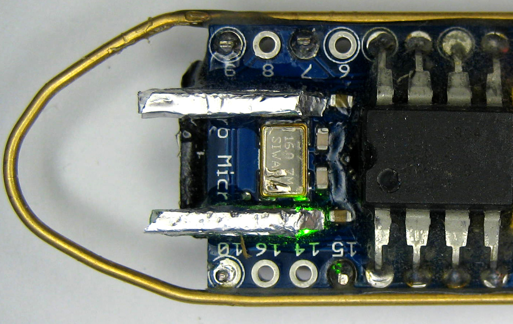 |
Its ok to have too long light
pipes. They will be cut off after you covered your board
with repair glue. If you have too short light pipes it will
be a pain to find them afterwards. The repair glue will be
in line with the button edge. In the picture on the left i
had to remove about 1 to 2mm. |
| 6.5 |
Let it cure |
If you know your repair glue you can just cut off stuff while its
curing. Sanding should be done only when its really cured after
about a day. Start with medium grade sanding paper (180). This
works for almost 90% of your work. Only at the very end you might
use very fine grades (400).
If you dont want to color and varnish it try to get a very smooth
surface. It will not collect any dirt then.
If you varnish it, you dont have to be very picky about a smooth
surface. Small screatches will be filled and cleared by the
varnish.
Color and Varnish:
To be on the safe side put a cover on top of the switch first.
Cut some plastic sheet and glue it to the edges of the button. Be
careful not to come close to the button itself. If you use
some soft glue then varnish and color stains can be removed easily
by removing the plastic. Always keep the usb connector down. If
you dont you might mess up the usb port. You can cover this too if
you want to. If you are carefull you dont need to cover it.
Design and hardware extensions used for Red Heart, Alien Artefact and Green Miracle : tc (thunderchild), Nov 2014 |